
Microscopes can be classified in several different ways; based on the interacting medium (light, electron etc), arrangement, number of lenses (simple, compound), or method of interaction between the sample and lens (probe, laser) etc. Below is a list of the different types of microscopes.
| Different Types of Microscopes |
|---|
| Simple microscope |
| Compound microscope |
| Stereo microscope |
| Metallurgical microscope |
| Polarizing microscope |
| Reflecting microscope |
| Phase contrast microscope |
| Interference microscope |
| Ultra-violet microscopes |
| Confocal microscopes |
| Darkfield microscope |
| Multi-photon excitation microscope |
| Super resolution microscope |
| Transmission electron microscope (TEM) |
| Scanning electron microscope (SEM) |
| Environmental scanning electron microscope (ESEM) |
| X-Ray microscope |
| Acoustic microscope |
| Inverted microscope |
Some types of microscopes could be the same microscope using different microscopy method which I have classified as a different type of microscope for the purposes of this post. Below we will discuss each one in more detail.
Classification by Lenses
Based on the number of lenses used for the magnification of a given sample, microscopes can be simple or compound.
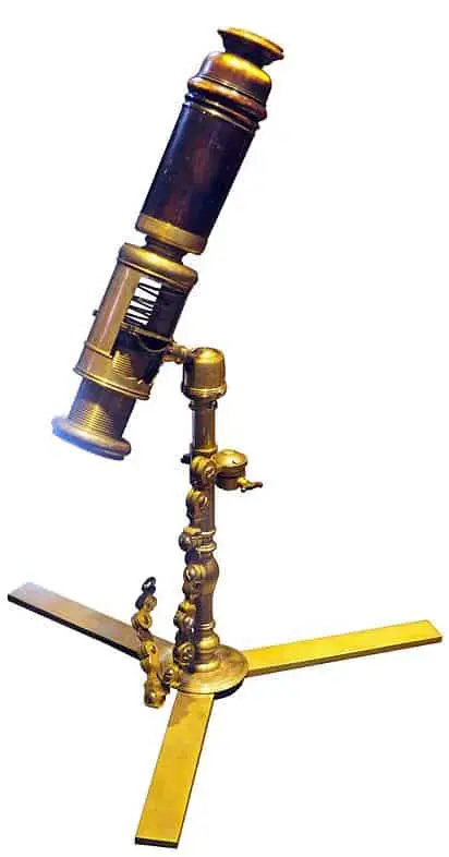
Simple Microscope
A simple microscope uses the magnifying power of a single lens or a group of lenses working together as a unit. The principle of a simple microscope is as simple as the name implies. A single lens that is called a loupe is placed at a particular distance from the specimen. The magnifying power of the device can then be expressed by the equation,
M= 1+D/F
Wherein, D is the distance between the specimen and the lens and F is the focal length of the lens. The lenses used in a simple microscope can vary between bi-convex (curved on both sides) or plano-convex (curved on one side) lenses. In the design of the device, the focal length is kept to a minimum to increase its magnifying power.
However, the maximum magnification achievable by these devices, even using today’s modern-day lenses is limited to 300X.
These microscopes are not commonly in use today due to their limited resolution. However, simple microscopes commonly called dissecting microscopes built with a single biconvex lens remains in use in biology labs.
The specimen to be magnified is placed on a small raised platform over the lens and a concave mirror is used to focus light onto the sample. The distance between the specimen and the lens can then be adjusted to produce an erect, virtual and magnified image.
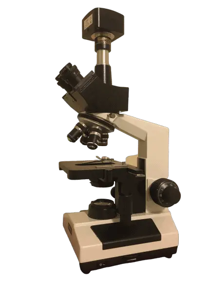
Compound Microscope
A compound microscope is built with two or more convex lenses. One or more objective lenses magnify the image which is then resolved using a secondary eye piece. Generally, the objective lens has a shorter aperture and focal length than the eyepiece.
The lenses are placed co-axially at two ends of an optic tube, with light-reflecting between the two; therefore these devices are also called reflecting microscopes.
An illumination system that transmits light is placed along with a condenser that focuses the light right beneath the specimen.
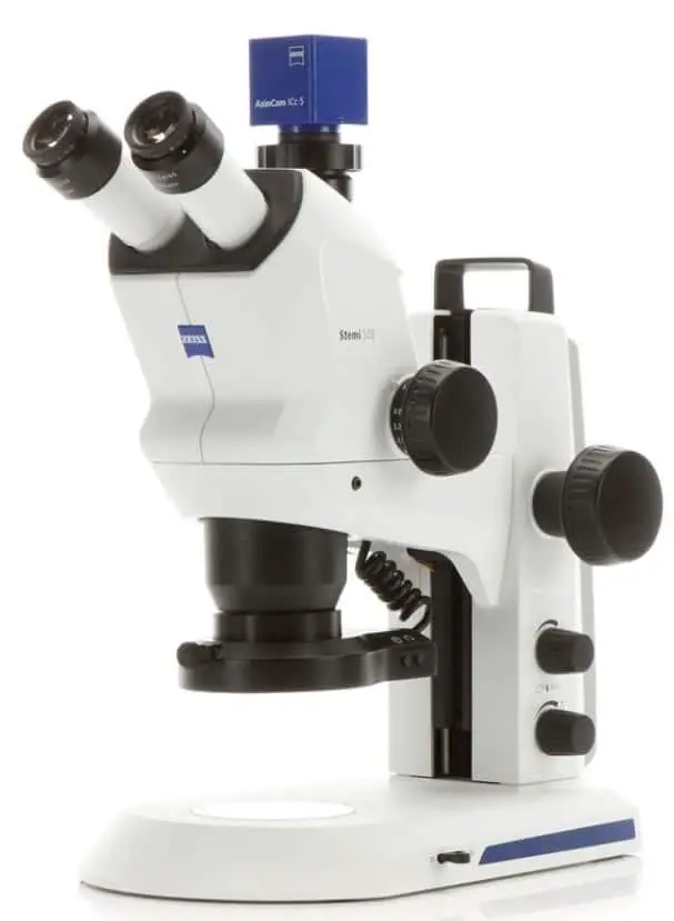
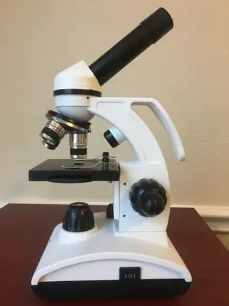
The specimen to be magnified is placed between the center of curvature and focal length of the objective lens to produce a real, inverted and magnified image. The inverted image is then resolved by the eyepiece to produce a virtual, erect and magnified image that can be seen by the observer. This is my personal microscope and it is the first actual microscope I purchased after playing around with some cheap microscopes. It has everything you need if you are looking at microscopy as a hobby.
The magnification produced by such a device can be calculated by the equation; M = L/ f0 (1+D/f ), where f0 and f are the focal lengths of the objective and eyepiece respectively. L is the length of the optical tube and D is the least distance between the eyepiece and objective that produces a distinct image.
Simple microscopes are riddled with chromatic aberration and limited resolution. However, these problems were only enhanced in the compound microscopes due to the additive defects of two lenses. In the early 18th century, chromatic aberration was resolved by the development of color corrected lenses which vastly improved the resolution of compound microscopes.
Basic compound microscopes are monocular, consisting of single optical tubes. A binocular tube may be fitted over the eyepiece to help the observer view the image through both eyes. However, the more advanced compound microscopes are designed with two independent objectives and eyepieces fitted at the ends of two optical tubes, enabling the observer to see a three-dimensional image.
Classification by Interaction between Specimen and Device
Optical Microscopy
In an optical microscope, the sample is illuminated by light, thus enabling its imaging. These can be simple or compound, depending on the magnification required. While simple optical microscopes can only magnify up to 300X, compound microscopes can magnify over 2000X. Furthermore, while simple optical microscopes are limited by a resolution of 1μm, compound optical microscopes can deliver a resolution over 0.2μm.
Illumination systems in optical microscopes can be classified as transmitted or incident illumination. Transmitted illuminators (brightfield/ darkfield) diffuse light through an opaque or transparent sample while incident illuminators simply light up the surface of a sample (fluorescent, stereoscopic). Both types consist of a light source such as an electric lamp or diode, along with a condenser that focuses the light into a bright, uniform beam across the specimen. The most commonly used optical or light microscopes are described below.
Polarizing Microscopes
Using polarized light to illuminate a sample can improve contrast thus providing better quality images. In the modified design, a polarizer is placed over the light source and an analyzer between the objective and the eyepiece.
Light is essentially an electromagnetic wave consisting of photons oscillating in multiple directions or planes. However, a polarizer restricts the oscillation to two perpendicular planes.
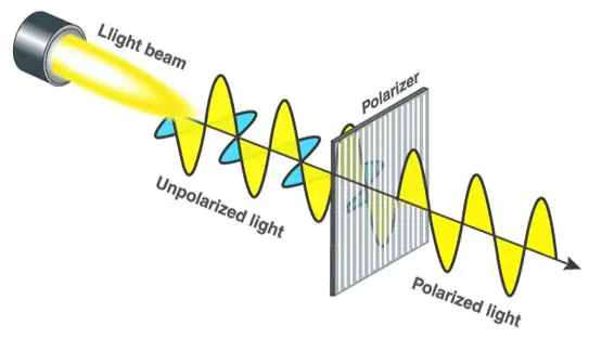
The light passing through the sample gets scattered once again. The analyzer then re-polarizes the light beam to form an image at the eyepiece. Polarizing microscopes require careful specimen preparation. The standard thickness of specimens that can be magnified using the device falls between 1 and 40 micrometers.
Polarized microscopes are commonly used to examine rocks, minerals, ceramics, fibers, polymers, biological molecules and structures. They have also found use in the material sciences, geology, chemistry, biology and even medicine.
Reflecting Microscopes
These devices contain an objective lens that reflects light as opposed to transmitting light. An incident illuminator is used to shine light on the surface of the sample, therefore reflecting microscopes may also be called incident light or epi-illumination microscopes. Only opaque samples can be viewed by incident illumination, therefore their use is limited.
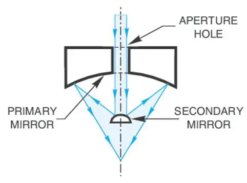
The device is built with two reflective components; a concave primary mirror and a convex secondary mirror. The secondary mirror merely reflects the image formed by the primary mirror to the eyepiece. The device is limited by both chromatic and spherical aberration. Yet, it has found use in many fields including, metallurgy, semiconductors and other manufacturing industries.
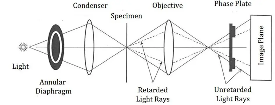
Phase Contrast Microscopes
Specimens of varied thickness refract light differently. This is the underlying principle of a phase-contrast microscope. An annular diaphragm attached to condenser focuses the beam of light into a hollow cone which travels through the specimen to reach the objective.
The light that does not pass through the specimen is of a different phase or wavelength from the light that passes through. This causes the structures that refract light to appear as dark spots against a bright background. Furthermore, structures that differ in thickness and morphology will refract light beams of varying brightness.
The device does not require staining; hence it is most commonly used in magnifying live biological samples such as cells. Since the cells do not have to be fixed or killed, their live dynamics can be observed under the microscope. Indeed, the phase-contrast microscope was monumental in the study of cell division and microorganisms that cause disease.
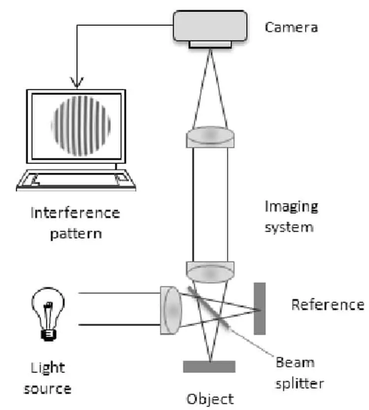
Interference Microscopes
The principle of interference microscopes is quite similar to phase contrast microscopes. However, not one but two independent beams are transmitted through the sample. The refracted beams which are each altered by the samples are combined to produce an interference pattern. The interference pattern can then be interpreted to distinguish structures in the specimen.
These microscopes can produce high contrast, well resolved, three-dimensional images of live, unstained specimens. Therefore, these devices have found use in the quantitative studies of bio-molecules and nanotechnology.
Ultra-violet Microscopes
These microscopes replace visible light with ultra-violet radiation to produce images with greater resolution and contrast. Higher magnification and resolution is enabled by the shorter wavelength of UV radiation. A most commonly use a variant of the ultra-violet microscopy is fluorescence microscopy described below.
Fluorescence Microscopy
Fluorochromes are substances that absorb energy and emit a light beam in the visible spectrum. Specimens that can be used in a fluorescence microscope include natural fluorochromes such as chlorophyll or specimens coated with fluorescent dyes such as FITC, acridine orange etc.
The illumination source usually produces light beams of short wavelength such as ultraviolet radiation which the specimen absorbs to emit visible light, thereby enabling the visualization of the sample.
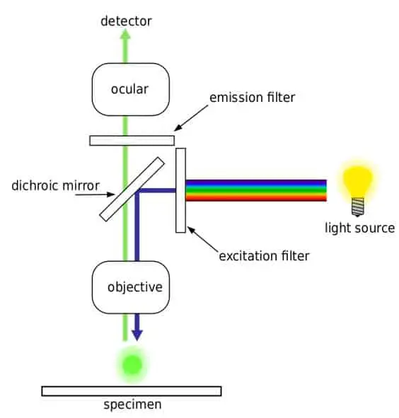
The image consists of bright colors against a dark background. These devices are most commonly used in biology to study structures within bio-molecules or examine micro-organisms and their interactions. A cell can also be stained with multiple fluorophores to distinguish between structures.
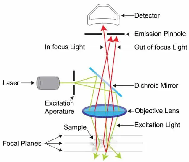
Confocal Microscopes
Confocal microscopes, commonly called confocal laser scanning microscopy uses the principle of fluorescence. However, the illumination source is a laser device which ‘scans’ or moves across the sample.
This produces layers of two-dimensional images which are combined by a computer to produce a three-dimensional image of the sample. The sample can be dyed with one or more fluorophores to better differentiate between the structures.
These devices are commonly used in biology to examine thick specimens which cannot be examined by other methods.
Brightfield Microscopes
These devices principally produce a dark image on a bright background. They contain a set of objective lenses placed over a rotating nosepiece. The magnification achievable through these devices range from 50X to 100X.
The illuminator is generally a bright bulb placed below the specimen. Light from the bulb is condensed and transmitted through the sample, finally collected by the eyepiece. The different parts of the specimen will change the path of light through reflection or refraction. Therefore, thicker structures appear darker.
These devices are generally used to examine microorganisms; however, they are hindered by a limited resolution. This can be overcome by immersing the specimen in a liquid of high refractive index such as oil. The liquid increases the refraction of light passing through the sample and thus increases the resolution of the image.
Darkfield Microscopes
The darkfield microscope uses the same design of a bright-field microscope but with the addition of a modified condenser. A small opaque ring placed over the illuminator focuses the light into a small hollow light which then passes through the sample.
As a result, all the light reaching the objective lens has passed through the sample. This produces a bright image of the specimen set against a dark background. These devices do not require the staining or ‘fixing’ of samples thereby enabling the magnification of live specimens.
Multi-photon Excitation Microscope
The two-photon microscope improves upon the design of both confocal and fluorescent microscope. These devices combine the scanning technique of confocal microscopes with fluorochromes and long-wavelength illumination to produce highly resolved images.
As the name implies, the illuminator produces two photon beams, one which scans the surface of the sample and another which transmits through the sample.
This device has enabled the visualization of specimens without staining, even whole organs and animals. However, the device is hindered by high costs and is therefore only found in laboratories.
Super Resolution Microscope
The super-resolution microscopy essentially combines several microscopy techniques to overcome the theoretical limit of resolution. This limit described by Ernst Abbe’s equation ranges between 200nm- 500nm. The super-resolution microscope brings down this range to 10 nm.
These devices can be broadly classified based on illumination source as patterned light illumination, or localized illumination. These devices have helped elucidate complex bio-molecular structures including visualizing interactions between cells.
Electron Microscopy
Apart from light waves, electrons can also be used to form images of a sample. Using electrons overcomes the resolution limit created by the wavelength of light. A high-speed beam of electrons is deflected through a sample using an electromagnetic field.
These devices have magnifying power exceeding 1,000,000X and are commonly used to examine bio-molecular and sub-cellular structures. The most commonly used electron microscopes are described below. For more on electron microscopes see Electron Microscopes Explained: From Physics to Images.
Transmission Electron Microscope (TEM)
A beam of electrons is transmitted through an ultra-thin section of the specimen to form an image. The interaction between the electrons and the sample section of varying opacity is interpreted to form an image on a detector such as a photographic film. For electrons to efficiently pass through a specimen, it must be of uniform thickness ranging between 20-100 nm.
These sections may be further stained with heavy metals such as gold or palladium to enhance the changes in density/ opacity across the sample. TEM also requires a complete vacuum or near-vacuum chamber for efficient transmission of electrons. Despite the stringent conditions required for its operation, the TEM is preferred by scientists as it can provide a magnification over 20 million fold!
The TEM set up typically consists of an electron gun that emits a high-velocity electron beam, a magnetic lens that condenses the beam and focuses it on the specimen, a detector which captures the transmitted electrons and an image recording system (photographic film, fluorescent screen) which converts the electron intensity to a magnified, real image. TEM is typically used in biology to examine cells, the structure of biomolecules and viruses that are too small to be imaged by other devices.
Scanning Electron Microscope
An SEM is used to examine the morphological differences in the surface of the specimen. The interaction between an electron beam and the specimen surface is interpreted to form a high resolution, three-dimensional image. The device uses low energy electrons and delivers a lower resolution than TEM, but they are very useful in examining the topography of solid surfaces.
The set-up is quite similar to a TEM, except for a secondary electron detector which examines the electrons emitted by the atoms of the specimen. The amount of electrons emitted by the atoms depends on the topography of the specimen. Unlike TEM, SEM does not require ultra-thin sections of samples, enabling the examination of even large, bulky specimens.
However, the conductivity or ability of the sample to transmit electrons can be increased by coating the specimen with heavy metals such as gold. Similar to TEM, SEM also requires a high vacuum environment which can be achieved by a combination of vacuum pumps and a power source.
Typically, the magnification achievable by these devices reach 20,000 fold. A cryogenic SEM is a modified SEM which allows for the examination of the crystal structure of biomolecules by freezing the sample. Apart from their use in biology, SEMs also play a crucial role in nanotechnology, forensic science, material science, semi-conductors, manufacture of integrated circuits, and soil and rock sampling.
Environmental Scanning Electron Microscope (ESEM)
Both SEM and TEM require extensive specimen preparation which may affect the natural state of biological molecules. The ESEM is a variation of the SEM which allows for the examination of wet or uncoated specimens in non-vacuum conditions.
The device allows for alterations in the environment of the imaging chamber, enabling visualisation of natural states. In principle, the set-up is quite similar to other electron microscopes but consists of a differential electron pumping system, transmission and detection device.
ESEMs have been used in biology and medicine to image live cells, in archaeology to preserve specimens in natural states, in material science and the manufacturing industry.
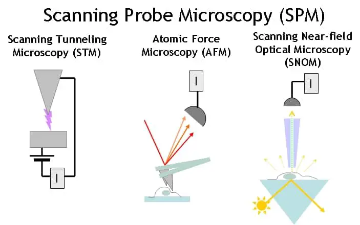
Scanning Probe Microscope
The scanning probe microscope interacts with the specimen without using any electromagnetic waves. Instead, a sharp thin probe physically interacts the surface of the specimen. The interaction between the probe and the sample is interpreted to form an image magnified over a million fold.
There are several variations of the scanning probe microscope including the scanning tunnelling microscope (STM) and atomic force microscope (ATM). An STM uses the quantum tunnelling of electrons between the probe and the sample to examine the surface of a specimen. The intensity of the current will depend on the distance aka the varying thickness of the specimen. This can effectively map the topology of the specimen at the resolution of individual atoms.
On the other hand, the AFM transmits a consistent current between the specimen and probe. The detector measures the variation in thickness as the probe tip passes over the sample. The Van der Waals, capillary, electrostatic and other forces of interaction between the atoms of the specimen and the probe cause the probe to move up and down.
This information is used by the detector to produce an image of the sample. These microscopes provide valuable information but are difficult to use and are therefore restricted to research laboratories.
X-Ray Microscope
The X-ray microscope essentially uses X rays to image the specimen. The set-up typically consists of an X-ray emitter which transmits the electromagnetic waves through the specimen. The variation in X-ray absorption across the specimen is interpreted to form an image that is detected using a film or charge-coupled device.
These devices have a resolution comparable to simple optical microscopes, they provide valuable information due to the ability of X-rays to travel through samples. Typically these are used to examine hidden structures in rocks, minerals, biological specimens and geological samples.
Acoustic Microscope
These devices use ultrasound waves to image the sample. The resolution of the devices is quite comparable to optical microscopes, however, sound waves can travel through large bulky samples to deliver information about their composition.
Importantly, sound waves are non-destructive and therefore preserve the structure of the sample while enabling imaging of internal features.
Samples do not need fixing or preparation to be imaged by acoustic microscopes. However, since air is a very poor transmitter of sound waves, samples are often immersed in other liquids such as water, alcohol etc.
In biology, these devices are often used to examine changes in bone density. Industrially, these devices are used in quality control to investigate cracks and voids, printing integrated circuits, investigate beneath layers of paint etc.
Classification by Application
Microscopes can be classified based on their design for specific applications. Although they follow the principles defined in previous sections, their design is specifically adapted for its purpose. A few examples are described below.
Biological Microscope
Microscopes used in biology typically contain specimen stages that can only mount microscope slides. The illuminator placed beneath the stage is combined with a condenser which focuses light on a specific spot in the slide.
These devices typically accommodate multiple objectives that provide a range of magnifications (4X to 1000X). Although they do not have high resolving or magnifying power, they are typically used in biology labs, hospitals and industries that image microorganisms (beer breweries etc).
Stereo Microscope
The stereo-microscope uses incident light to illuminate a sample. Two sets of eyepieces and objectives produce a three-dimensional image through two independent optical paths. The magnification it achieves is quite low, up to 50X. Since it visualizes the light reflected from a sample, it is best used to magnify opaque, solid and thick specimens such as coins, fossils, minerals, insects, flowers etc.
It has also found use in microsurgery, building circuits, and in the manufacturing industry to inspect specimens for cracks and provide quality control. An additional advantage of this device is it does not require slide preparation, allowing the magnification of objects too big for a compound microscope.
Metallurgical Microscope
These devices, as their name implies, are used to examine the surfaces of metals and other minerals. A vertical illumination source also called incident illumination is used to image the sample by placing it below the eyepiece. The light passes through the objective onto the sample.
The light reflected from the sample is refocused by the objective, is transmitted back to the eyepiece. Since light reflected from the sample is required to visualize the sample, the specimen must be highly reflective, containing a flat, polished surface. These devices have found use in forensic science, diagnostic microscopy and metallurgy.
Classification by Structure
Based on the location of the illuminator and the path of light through the sample, microscopes can be classified as upright or inverted.
Upright Microscope
In an upright microscope, the light source is placed below the specimen stage. The light travels through the specimen before being transmitted through the objective lens.
The observer views the image from the top, through the eyepiece placed over the device. These devices are hindered by low resolution compared to inverted microscopes which work with shorter optical tubes. These devices are commonly used in biology to image cells and tissue sections.
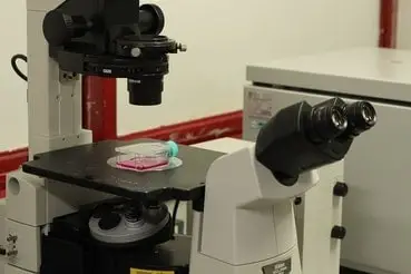
Inverted Microscope
In an inverted microscope, the illuminator and condenser are placed over the specimen stage, pointing downwards. The objective lens is placed below the specimen, pointing upwards. Consequentially, the specimen is observed through the bottom. This inverted design allows for higher resolution and contrast imaging.
Additionally, this method maintains sample sterility as there is no contact between the sample and the objective lens. Hence, these devices are preferred for live-cell imaging in culture mediums.
Takeaways
Microscopes come in many different configurations and work using different scientific principles. In this article we have looked at all the ways we can categorize microscopes by different characteristics. I hope this article has given you a glimpse into the many types of microscopes used to make some of the most ground-breaking discoveries of today and tomorrow!
References
- W.E Seeds et al., A Simple reflecting Microscope. https://www.nature.com/articles/164228a0
- Gunther et al., Scanning near field acoustic microscopy. https://link.springer.com/article/10.1007/BF00694423
- John Bozzola, Electron microscopy; Principles and techniques. https://books.google.co.in/books/about/Electron_Microscopy.html?id=zMkBAPACbEkC&redir_esc=y
- Wiesendanger et al., Scanning Probe Microscopy. https://www.cambridge.org/core/books/scanning-probe-microscopy-and-spectroscopy/92B4C6E961A09D23635AF7A3DC62FC42
- Galbraith et al., Super resolution microscopy at a glance. https://jcs.biologists.org/content/124/10/1607.short
- Uluc et al., Operating Microscopes; Past, present and future. https://thejns.org/focus/view/journals/neurosurg-focus/27/3/article-pE4.xml
- Howells et al., X-ray Microscopes. https://www.jstor.org/stable/24936794?seq=1
- Masters et al., Ernst Abbe and the foundation of scientific microscopes. https://www.osapublishing.org/opn/abstract.cfm?uri=opn-18-2-18
- Schenke-Layland et al., Two photon microscopes. https://www.sciencedirect.com/science/article/abs/pii/S0169409X06001268
- Lichtman et al., Fluorescence Microscopy. https://www.nature.com/articles/nmeth817
- Pluta et al., Advances in Light Microscopy. https://books.google.co.in/books/about/Advanced_light_microscopy.html?id=j2XwAAAAMAAJ&redir_esc=y